More of Contemporary
Practices
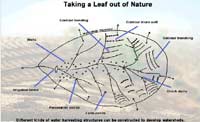
A look at some of the common practices adopted to harvest rain...
Check
dams
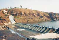
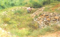
A check dam is generally constructed on small streams and long gullies
formed by the erosive activity of water. The ideally a check dam
is located in a narrow stream with high banks.
A check dam serves many purposes.
- It cuts off the runoff velocity and reduces erosive activity
- The water stored improves soil moisture of the adjoining areas
and allows percolation to recharge the aquifers
While constructing a series of check dams on along stream course,
the spacing between two check dams should be beyond their water
spread. The height of the check dam should be such that even during
the highest flood, water does not spill over the banks.
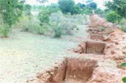
Contour trenches
Contour trenches are used both on hill slopes as well as on degraded
and barren waste lands for soil and moisture conservation and afforestation
purposes. The trenches break the slope and reduce the velocity of
surface runoff. It can be used in all slopes irrespective of rainfall
conditions (i.e., in both high and low rainfall conditions), varying
soil types and depths.
Specifications: Trenches can be continuous or interrupted. The interrupted
one can be in series or staggered, continuous one is used for moisture
conservation in low rainfall areas and require careful layout. Intermittent
trenches are adopted in high rainfall areas. The trenches are to be
constructed strictly on contours irrespective of the category.
Layout: The size of the trench depends upon the soil's depth. Normally
1,000 sq cm to 2,500 sq cm. in cross section are adopted. The trench
may be of 30 cm base and 30 cm top width and square in cross section
or it can be trapezoidal with side slopes 1:1. Based on the quantum
of rainfall to be retained, it is possible to calculate the size
and number of trenches.
|
Slope of the land
|
20 %
|
45 %
|
50 % (with soil of
30cm depth )
|
60 % (with soil of
30cm depth)
|
| Horizontal interval |
7.5m |
9m |
7.5m |
9m |
| Vertical interval |
1.5m |
4m |
3.75m |
5.85m |
Bunding
Bunds are small earthen barriers provided in agricultural lands with
slopes ranging from 1 to 6 percent. They control the effective length
of slope and thereby reduce the gain in velocity of runoff flow to
avoid gully formations. Bunds are constructed with the following objectives:
- To increase the time of concentration of rainwater where it
falls and thereby allowing rainwater to percolate into the soil
- Converting a long slope into several ones as to minimise velocity
and thereby reducing the erosion by runoff water
- To divert runoff either for water harvesting purposes
Types of bunds
a) Graded bunds: Graded bunds are constructed in medium to high rainfall
area - having annual rainfall of 600mm and above - and in soils with
poor permeability or those having the crust formation tendency.
b) Contour bunds: Contour bunds are constructed in relatively low
rainfall areas- having annual rainfall of less than 600 mm ; particularly
in the areas having light textured soils. They are essentially meant
for storing rainwater received during a period of 24 hours at 10 years
recurrence interval. The major considerations are maximum depth of
water to be impounded, design depth of flow over waste weir and desired
free board
Contour Stone wall
It is constructed with
stones across the hill slopes thereby intercepting the surface runoff.
These terraces help in retarding the soil loss and conserving soil
moisture. Spacing of such stone walls are not rigid. Spacing ranging
from 10 m to 30 m can be adopted depending upon slope of the terrain.
For the construction, a shallow trench has to be dug and the stones
collected and packed directly on to the foundation and in the super
structure to form the terrace. The stones should be properly interlocked.
The soil excavated to form the foundation for the terrace is used
for forming a small bund on the upstream side of the terrace. Terrace
is stabilised by planting suitable vegetation on the bund.
Gully control
Gully erosion generally starts as small rills and gradually develop
into deeper crevices. Ravines are a form of extensive gully erosion.
Gully erosion not only damages the land resources but the same time
contribute larger amount of sediment load to river system.
Classification of gullies:
For the purpose of gully control measures gullies are classified
based on several factors. One method takes into consideration the
gully depth and catchment area. The following table give the classification
of gullies:
| Description |
Gully
depth |
Catchment
area |
| Small |
1m or less |
2 ha. Or less |
| Medium |
1 to 5m |
2 - 20 ha. |
| Large |
Greater than 5m |
Greater than 20 ha |
Gully plugs are earthen embankments usually constructed for blocking
the active and erosion prone gullies for their stabilisation.
a) brushwood dams
b) loose rock dams
c) woven wire dams
Use locally available vegetative cutting in their construction.
In the woven dam a wire mesh is used to hold the stone in place.
All the check dams involving stones are to be adopted in areas where
stones are available easily and in plenty. The rock fill dam and
the woven wire dam are more lasting than the loose rock dam. There
are no standard principles of the design of these structures. These
are to be designed and constructed based on the needs and availability
of materials in a given situation. The overall height of temporary
check dams use for this purpose should not be more than 75 cms;
an effective height of about 30 cms is satisfactory.
Sub-Surface Dams
Groundwater dams are structures that intercept or obstruct the natural
flow of groundwater and provide storage for water underground. They
have been used in several parts of the world, notably India, Africa
and Brazil. Their use is in areas where flows of groundwater vary
considerably during the course of the year, from very high flows following
rain to negligible flows during the dry season.
The basic principle of the groundwater dam is that instead of storing
the water in surface reservoirs, water is stored underground. The
main advantages of water storage in groundwater dams is that evaporation
losses are much less for water stored underground. Further, risk
of contamination of the stored water from the surface is reduced
because as parasites cannot breed in underground water. The problem
of submergence of land which is normally associated with surface
dams is not present with sub-surface dams.
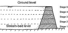 Figure - 1
 |
|
There are two main types of groundwater dam: the sub-surface dam
and the sand storage dam. A sub-surface dam intercepts or obstructs
the flow of an aquifer and reduces the variation of the level of
the groundwater table upstream of the dam. It is built entirely
under the ground (see figure 1).
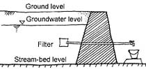 Figure - 2
 |
|
The sand storage dam is constructed above ground. Sand and soil
particles transported during periods of high flow are allowed to
deposit behind the dam, and water is stored in these soil deposits
(see figure 2). The sand storage dam is constructed in layers to
allow sand to be deposited and finer material be washed downstream
(see figure 3).
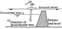 Figure - 3
 |
|
A groundwater dam can also be a combination of these two types.
When constructing a sub-surface dam in a river bed, one can increase
the storage volume by letting the dam wall rise over the surface,
thus causing additional accumulation of sediments. Similarly, when
a sand-storage dam is constructed it is necessary to excavate a
trench in the sand bed in order to reach bedrock, which can be used
to create a sub-surface dam too. Groundwater dams are built across
streams or valleys. A trench is dug across the valley or stream,
reaching to the bedrock or other stable layer like clay. An impervious
wall is constructed in the trench, which is then refilled with the
excavated material. Various materials may be used for the construction
of groundwater dams. Materials should be waterproof, and the dam
should be strong enough to withstand the imposed soil and water
loads. Dams may vary from 2 to 10 metres high. Materials include
compacted clay, concrete, stones and clay, masonry wall or plastic
sheets.
The reservoir is recharged during the monsoon period and the stored
water can be used during the dry season. Excess water flows over
the top of the dam to replenish aquifers downstream. Water may be
obtained from the underground reservoir either from a well upstream
of the dam or from a pipe, passing through the dam, and leading
to a collection point downstream (see figures 1 and 2). Groundwater
dams cannot be a universally applicable as these require specific
conditions for functioning. The best sites for construction of groundwater
dams are where the soil consists of sands and gravel, with rock
or a permeable layer at a depth of a few metres. Ideally the dam
should be built where rainwater from a large catchment area flows
through a narrow passage. The Central Ground Water Board has sited
and constructed a number of sub-surface dams in Kerala in the 1980s.
Presently, Shri Vivekananda Research and Training Institute (SVRTI),
under the guidance of K C B Raju is involved in constructing groundwater
dams in Kutch district of Gujarat.
Source: Dr. K.C.B. Raju, Nanda Gautam, 492 10th Cross Sadashiv Nagar,
Bangalore - 560 080
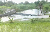
Percolation ponds
A percolation pond, like an irrigation tank, has a structure
to impound rainwater flowing through a watershed, and a wasteweir
to dispose of the surplus flow in excess of the storage capacity of
the lake created. The section of the bund is similar to that of an
irrigation tank, except that the cut-off trench is taken to a depth
equal to half the height of the bund. The purpose of the cut-off in
the case of the percolation tank is just to prevent erosion of the
downstream slope of the bund due to piping. The cut-off should be
shallow enough to permit the percolating water to pass downstream
into the aquifer. The percolation tank bund has a hearting and a casing,
and is provided with stone pitching on the upstream face and turfing
on the downstream slope. A masonry waste weir is also necessary to
pass surplus water. Drains are provided under the bund to lead water
percolating into the bund safely downstream. The percolation tanks
of Maharashtra have, on an average, a larger storage capacity than
the rapats of Rajasthan. The storage capacity of percolation pond
is around 30 to 60 million litres
|